NON-RECTANGULAR BOX
Tools and Skills: Rapid Prototyping, CAD in Fusion 360, laser cutting, rastering, kerf bending
Project Brief
Design and create a sealed box with at least one face that is non-orthogonal to the other sides. NO ADHESIVES ALLOWED — the box must be assembled using machine screws, nuts, and tabs.
Challenges
This project had an extremely fast turnaround, but I still wanted to make a box that was unique and visually compelling. My biggest challenge was finding an appropriate balance.
Results
I had a lot of fun with this project! I wanted to incorporate new laser cutting techniques I’d learned about into my design in a way that was functional but also playful.
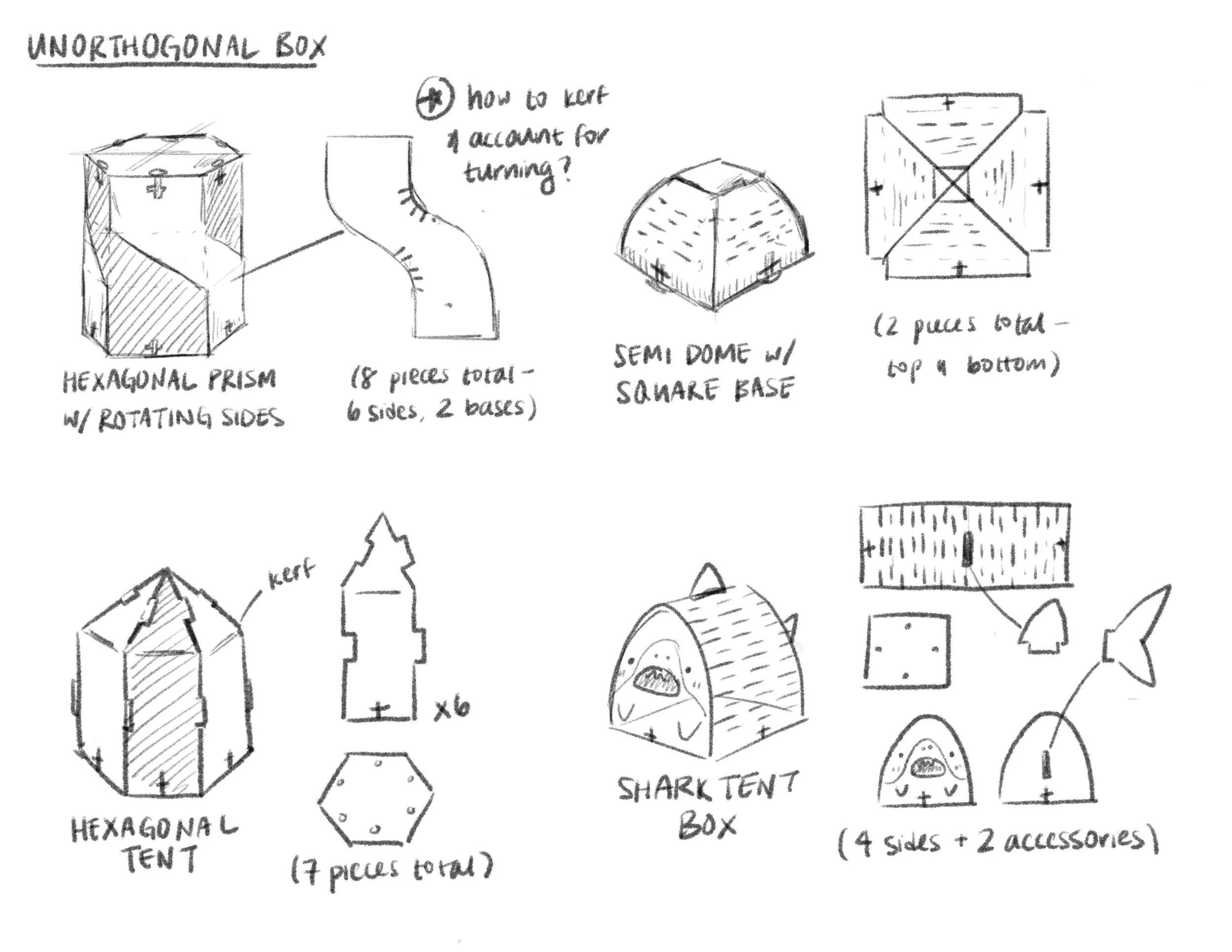
CONCEPT SKETCHES
In learning about laser cutting, I’d learned about a technique called kerf bending, which makes a stiff material such as wood flexible by putting a lot of small cuts in it. I wanted to incorporate this technique into my design, and I ultimately decided on the shark box because it was the most appropriately scoped for the short time frame for this project and because it was the most exciting to me.
This was my first time creating a full assembly with CAD! While I was able to get the overall shape, dimensions, and connection points down, what my CAD didn’t account for was how the wood would behave when bent. This was something I had to keep in mind when testing my design.
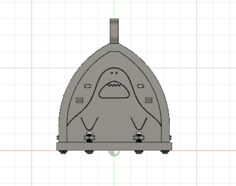
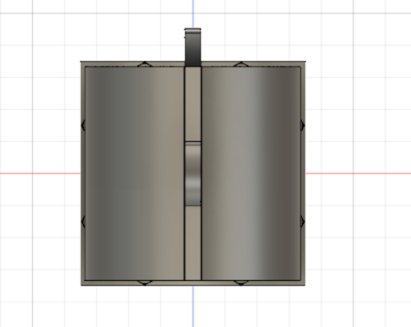
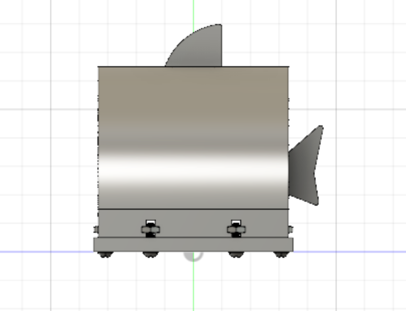
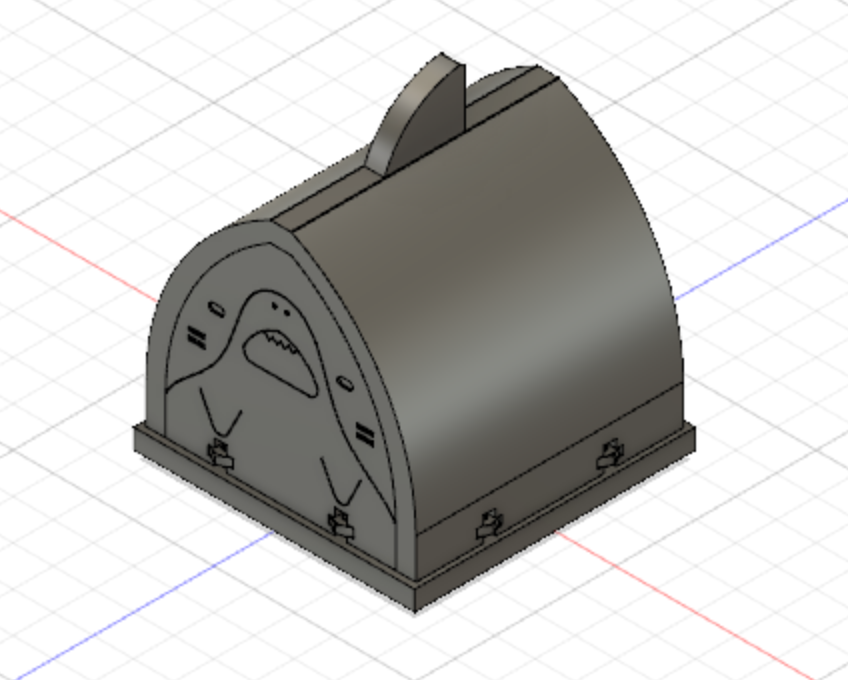
CAD ASSEMBLY
LASER CUTTER TEMPLATES
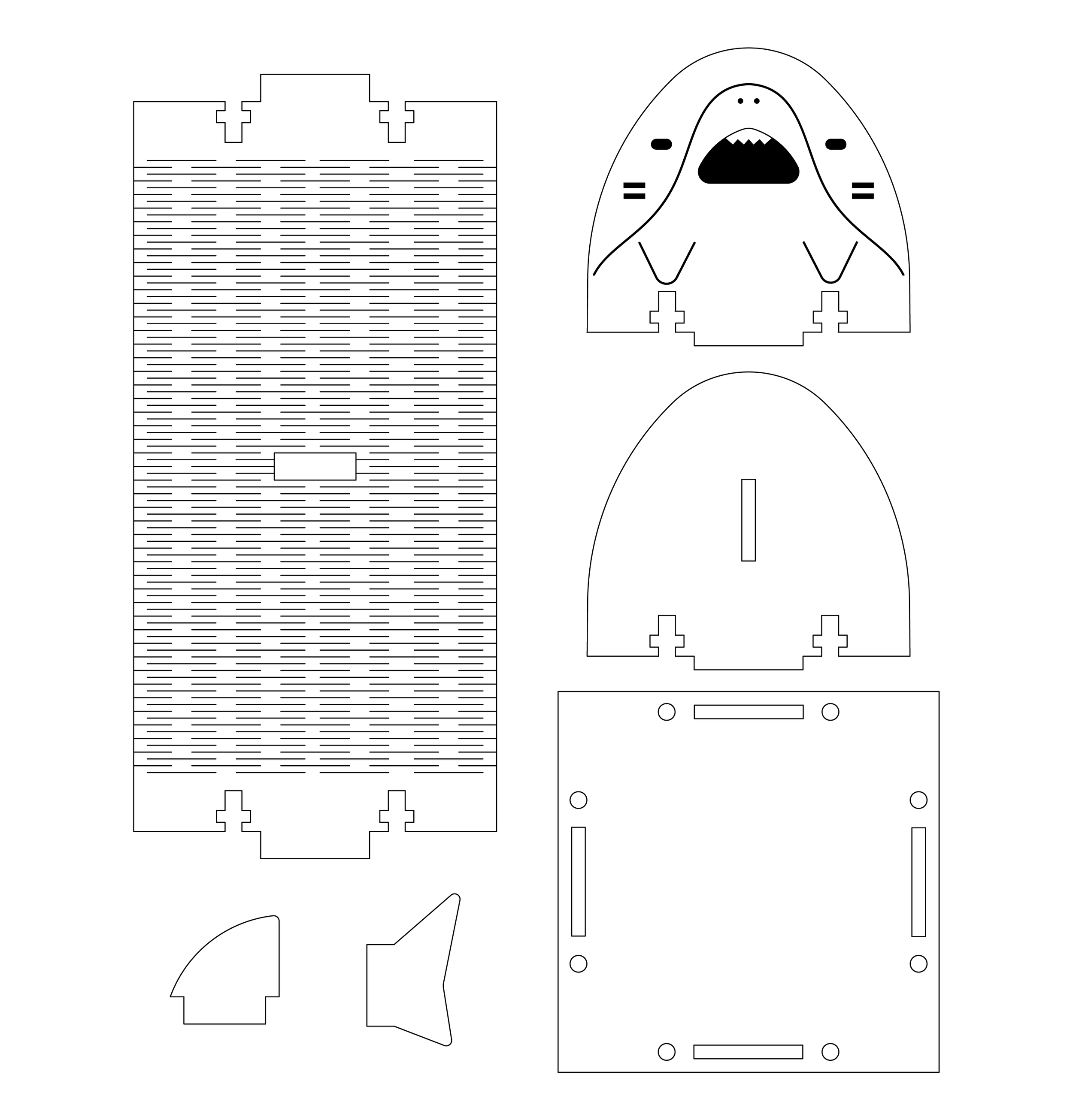
This is a black and white version of the templates that were given to the laser cutter. In testing, I found that front and back faces needed to be significantly more rounded than I’d initially designed for the CAD since the bend radius of the wood was larger than I thought it would be.
The long left piece was the one to be kerf bent, hence the many, many small slits. Notice the front face has bold lines outlining the sharks features — these indicate where the laser cutter should raster, or essentially “color in,” the surface of the material without cutting all the way through.
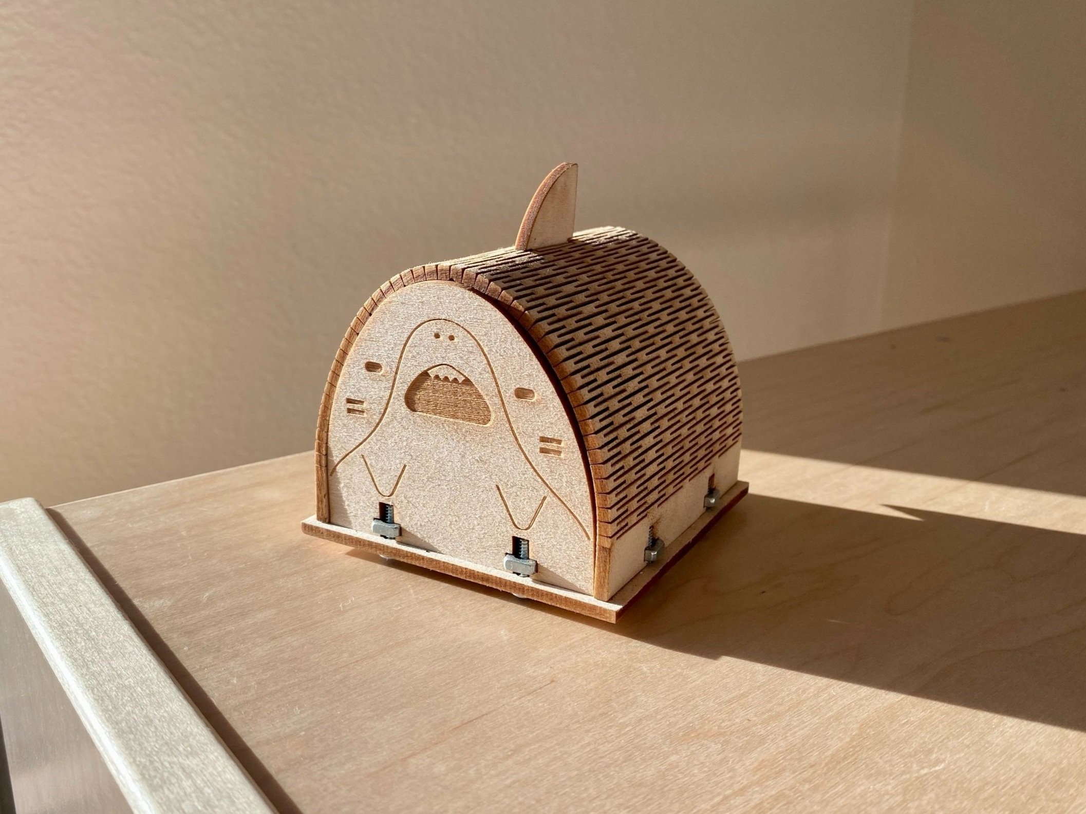
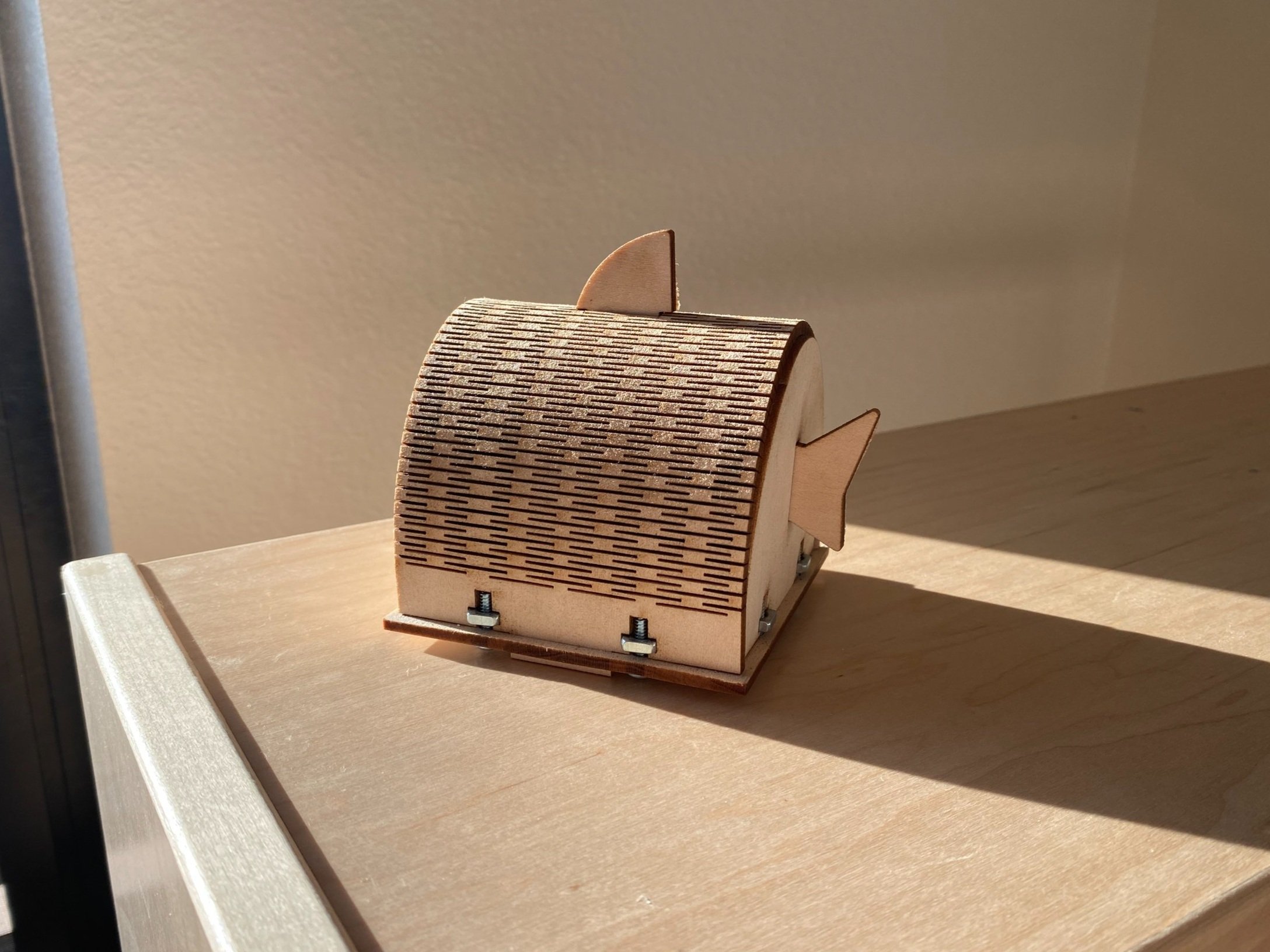
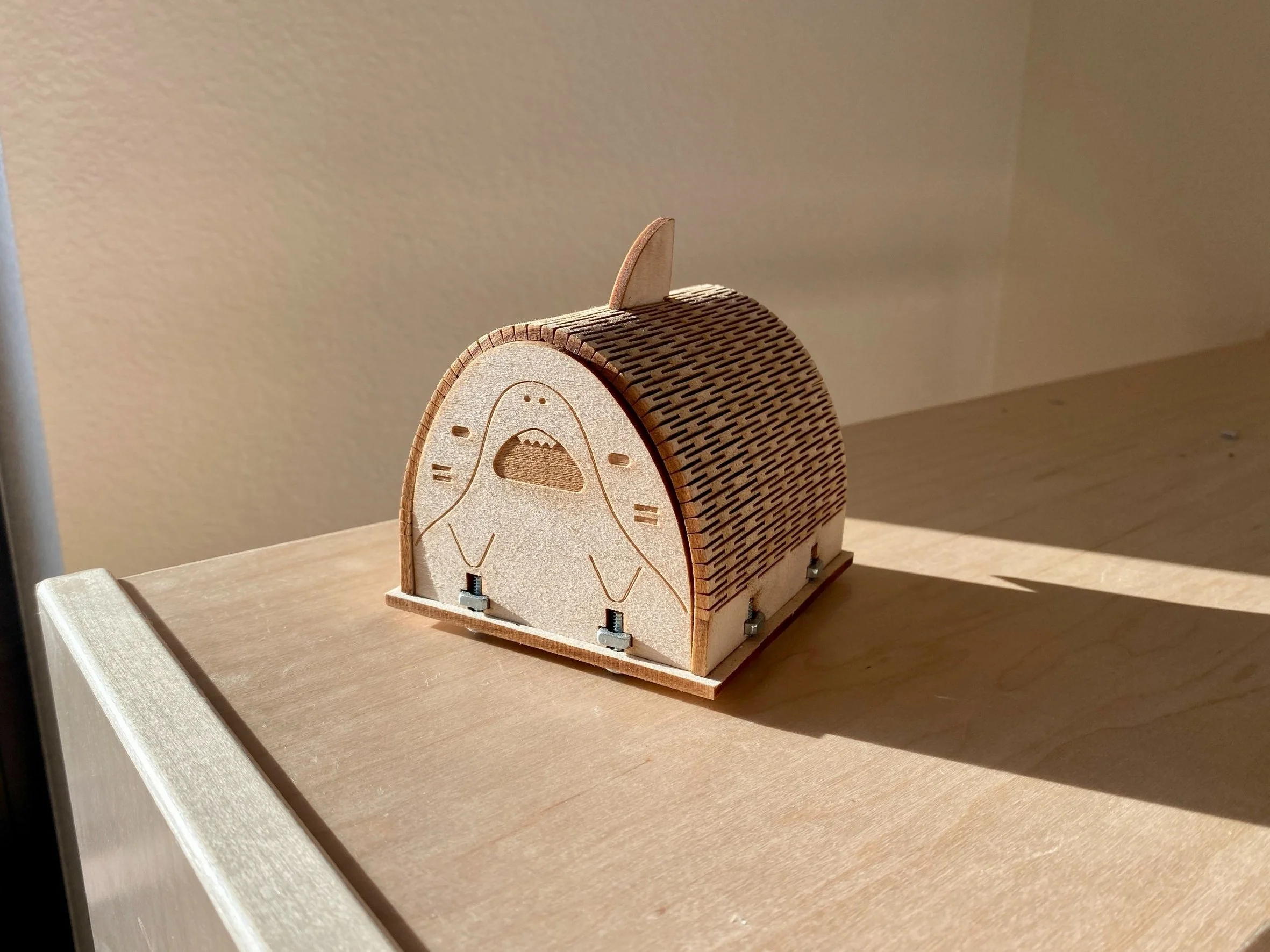
FINAL PRODUCT
The final shark box! I noticed that the front and back faces would tilt outward a little, which may mean that the tolerances of the connector tabs are not as tight as they should be. If I were to revisit this project, I would pay more attention to this and/or find a way to better stabilize the front and back faces, but since this was a very short project, I wasn’t too bothered by it. In fact, I’m very happy with the result!